 Dark Ages Re-Creation Company


Date: 12 Oct, 2008
Location: Vinderheima
See also: http://www.warehamforge.ca/ironsmelting/
Premise:
Experiment Notes - Norse Short Shaft Smelter in a frame
| Diameter: | 25 cm | Stack above Tuyure: | 45 cm | Tuyure Diameter: | 1" (2.6 cm) I.D. |
| Tuyure Distance above floor: | 20 cm | Tuyure Angle: | 20° | Tuyure Penetration into stack (start/finish) | N/A |
| Leader | Neil Peterson / Darrell Markewitz |
| Staff | Ken Cook |
| Recorder | Darrell Markewitz |
| Strikers | Neil Peterson / Ken Cook |
| Construction | Ken Cook / Darrell Markewitz |
| Total Charcoal | 46 Kg | Weight of Bloom | 4.9 Kg | Total Elapsed Time: | 6:30 |
| Total Ore | 23 Kg (8 Kg Virginia Rock ore / 15 Kg Taconite) | Weight of Slag: | ?? | Bloom Quality | mild steel |
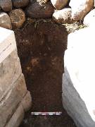
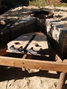
When the original working area was laid out, it was designed to allow for two smelters to be installed side by side. The earth bank that defines the western edge of the working area was retained by a line of concrete blocks, which could be easily moved to make alterations. Two rail road ties were used to block in the 2 m x 2m overall size indicated at Hals. On the actual above ground sod construction, this would be a log crib. With the length of the ties actually a bit more than required (and lots of stones!) the rear dimension was set using a row of rocks. By removing three stacks of the retaining wall blocks, there is about the correct opening for the front V of a working area leading back to the smelter front wall. Measuring from the current work surface to the tops of the two rail ties, establishes about the correct height proposed for the Icelandic construction.
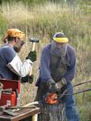
After about 6 hours work, the bank was cut back and concrete blocks used to secure the walls to create the V shape work area. The space between the V of the block walls is the length of a standard block (about 25 cm).
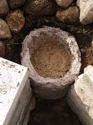
The next task was to first cut a rough cylinder into the earth bank, then build the clay shaft of the furnace. As with past construction, the clay cobb was composed of commercial powdered potter's clay mixed with about 50 % by volume of chopped straw, cut to 5 - 8 cm lengths. A space for the tap arch was determined by framing it with a standard brick about (20 cm long x 10 high) As each course of clay cobb was built up, loose earth was hand packed into the irregular space between the exterior wall surface and the cut earth. To balance this inward force and stabilize the thinner walls, course sand was used to fill the interior space to the identical level. It was also hoped that the sand would help to wick off some of the moisture from the wet clay. As the cylinder reached the level of the working platform (about 65 cm total height) a ring of stones was placed to support the upper edge.
The last step in completing the working platform was to top off the surface with about 5 cm of clean course sand.
The bellows plate was made up of a 50 / 50 mix of powdered clay and shredded, dry horse manure. Replacing the straw with manure gives a finer texture to the finished plate. The plate measured 20 cm wide by 25 cm tall, overall 3 cm thick.
The structure was left to stabilize for a few hours, then the sand inside was scooped out. As the lower area was reached, the brick supporting the tap arch was carefully pulled out, allowing the balance of the sand to be cleared. The brick was then replaced, set so the holes through its center would lead into the shaft. At this point a very gentle split wood fire was started inside the shaft. This process of adding a handful of splits at a time would continue for several hours. At the end of the evening, a metal cover was placed on the open top of the shaft so the coals created would slowly bake dry the smelter over night.
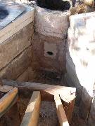
The next morning the whole smelter shaft was found to be still warm to the touch, and was baked dry and hard. A layer of ash and fragments of unburned charcoal was found to a depth even with the tap arch. A dry wall saw was used to lay out a rectangle the same size as the bellows plate, and then that portion of the smelter wall was cut away. The supporting brick was removed from the tap arch so the ash from the drying fire could be scooped out.
The bellows plate was also dry and hard, and was found to have curled up slightly at its edges (from the aggressive drying over the fire). The plate was trimmed slightly to fit, then installed into the smelter. It was positioned so that it would sit flush with the inside smelter surface (thus slightly recessed on the outer face). Fresh clay was used to mortar in the plate to the smelter walls. There was some concern at that time because of the difference between the consistency between the dry surfaces and this fresh clay. It was expected that considerable shrinking and eventual peeling away of the joints might lead to problems latter on in the firing sequence. (Which did prove to be the case.)
Finally a hole was cut into the bellows plate. The position was determined from the earlier layout drawings, the centre roughly 25 cm above the base line. The size of this hole was 8 cm, sized to leave 1.5 cm clearance around the exterior diameter (at 5 cm) of the standard ceramic tubes used for tuyeres.
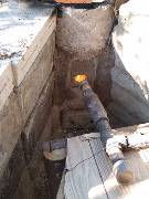
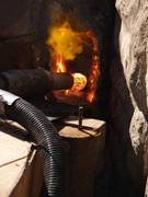
As one of the objectives was to determine the work pattern (and problems) with the layout including a human powered bellows, the space for this equipment was determined by positioning the frame required to support a Norse style double bellows of suitable size. The space was then simulated with a full sized cut out in the same location. The standard electric blower was then use to provide the required air, with a flexible pipe attached to the normal T fitting. The working end consisted of one of the commercial ceramic tube tuyeres (2.5 cm interior diameter). The measured angle on the air pipe was 15 degrees down. The gap between the tip of the air pipe and the surface of the bellows plate was established by sound (adjusting for the loudest and 'throaty-est' roar). Once this was established, the air pipe was wired into place on the wooden frame. The resulting gap was about 3 - 4 cm determined with an air flow estimated at 740 litres per minute.
As with past smelts, a preheat phase using split wood was applied first. This was done using natural draft for one hour and ten minutes, followed by a brief period with gentle air flow from the blower supplied. No specific base was set for the furnace, the ash and mostly consumed charcoal from the preheat phase was left in place. (The normal practice is to use a layer of charcoal fines to define a floor for the furnace at a measured distance below the tuyere.) The total preheat was one hour and 18 minutes, at this point the smelter was filled with rough charcoal and a full air blast was started. The furnace would require about 45 minutes operation to completely ignite the working column to the top.
At the start of main sequence the consumption rate was about 13 minutes per standard bucket (measured at 1.85 kg), so charging with ore was started.
For this smelt, it was decided to use a combination of the remaining industrial taconite plus the poor quality Virginia rock ore. The rock ore was considered to be a bit low in iron content, and so was added first to establish a working slag bowl. Additions were measured 'by the scoop', with the actual weights determined mathematically later. Larger charges were used right from the start, being 4 scoops (1.1 kg total) within each bucket of charcoal. After a total of about 8 kg of the rock ore was added, charges were switched to the much higher iron content taconite. (Both materials had been roasted and crushed to the normal 'rice to half pea' size.)
Just about the point were the switch was being made to the second ore type, problems were starting to be encountered with the function of the blow hole air system.
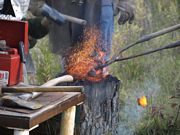
After the addition of roughly the first 8 kg of ore, (about 6 kg fallen to tuyere level) the top of the slag bowl could be easily seen just below the bottom edge of the blow hole. Several attempts were made to gather excess slag on to a metal rod to lower the level. This met with limited effect, largely due to limited skill and experience of the operators. A film of hardened slag could be seen developing to the left edge of the blow hole. Clearly the slag was starting on its way to blocking the air flow. Unfortunately, an especially large gather of slag slid off the rod right at the hole's mouth, completely blocking the blast. Immediately, the temperature in the whole furnace began to plummet. With some frantic activity, that slag was shoved into the centre of the furnace, and the ceramic tube was pushed through the bellows plate to convert the smelter into an insert tuyere type.
This effectively halted two of the primary objectives of the experiment (use of bellows plate and blow hole combination), but did recover the furnace temperatures back up to correct operating levels. After about 20 minutes the burning rate had returned to the 13 minutes per charge established before this disaster, and ore charges were resumed.
At this point the air pipe system was hung from an overhead support with wire so the bellows frame could be removed out the way. It was then possible to open the tap arch and clear the wood ash from underneath the slag bowl. Almost immediately, the furnace began self tapping with the typical late stage dark black, solid and fluid slag.
The charges of taconite were denser than the earlier rock ore, with 1.6 kg per bucket being added roughly every 13 minutes for the balance of the smelt (roughly 1 : 1), an additional 15 kg.
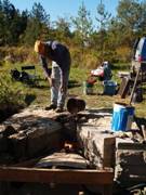
When the last ore was added, the remainder of a charcoal bucket was used to cover it, and the furnace taken straight into the burn down phase. The extraction started with an attempt to pull from the top. The charcoal was allowed to burn down to quite close to the top of the slag bowl. For this reason, the debris field was quite limited on the upper working platform. Neil started the extraction process, but was having some problems assessing just where the bloom had formed and for that reason (plus more limited experience) had considerable problems. The initial compaction and loosing of the bloom with the thumper in place inside the smelter was therefore not as effective as might have been desired. Through this effort, the temperature inside the furnace was dropping, and the slag mass slowly congealing. Eventually it proved necessary to switch to a bottom exaction through the tap arch. By the time the bloom was eventually pulled from the smelter, it was in fact too cold to undertake any significant consolidation. It was possible to knock free the loose 'mother' and shape it to a rough brick shape.
The next morning, the tools were cleared away and a closer look was taken of our working area. The layer of clean sand that had been deposited over the upper platform and to the front of the smelter slot made assessing working patterns easier. - There was very little debris of any kind deposited on the upper working platform. This was due partially to the more complete burn down to the top of the slag bowl than had been done in the past. This was not entirely intentional, but more a result of a longer time getting organized by a less experienced operator who started the extraction process. Less partially consumed charcoal remained to be scooped away, also leaving a higher percentage of 'slag drips' mixed in with that material.
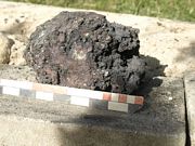
The production aim for this experiment was for a 3 - 5 kg bloom, similar to those suggested for Hals (size in range of 15 x 15 x 10 cm). Despite the near disaster of the blocked air hole, the team was able to apply past experience to salvage the smelt, producing a 4.9 kg bloom.
 |
 |
 |
 |
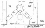
| Plan view | Cut out for smelter | Third layer | Bellows plate |
 |
 |
 |
 |
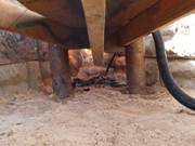
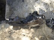
| Test bellows | New air system | Under bellows view | Cracks around bellows plates |
 |
 |
 |
 |
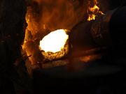
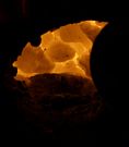
| Blockage | Smelter insides | Better view | High slag level |
 |
 |
 |
 |
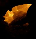
| Collecting a gather | Smelter after a gather | Puntil with slag | Another gather |
 |
 |
 |
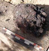 |
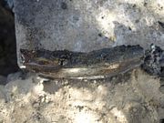
| Working the bloom | Working the bloom | Working the bloom | Finished bloom |
 |
 |
 |
|
| Finished bloom | Bellows plate | Bellows plate |
| CLOCK | ELAPSED | EVENT | AIR | CHARCOAL | ORE | ||||||
| UNIT | COUNT | TOTAL | UNIT | COUNT | TOTAL | ||||||
| gage | LpM | P | bucket | kg | scoop | kg | |||||
| 1.85 | note | ||||||||||
| 12:00 | start wood splints pre-heat | ||||||||||
| 13:10 | 1:10 | gentle air applied | *400* | ||||||||
| 13:18 | 1:18 | full with rough charcoal | 90 ? | 740 ? | 4 | 4 | 4 | 7.40 | |||
| 13:35 | :17 | 1 | 5 | 9.25 | |||||||
| 13:48 | :13 | 1 | 6 | 11.10 | |||||||
| 14:02 | :14 | 1 | 7 | 12.95 | |||||||
| 14:03 | first ore addition - Virginia Rock | ||||||||||
| 14:15 | :13 | 1 | 8 | 14.80 | 4 | 4 | 1.1 | ||||
| 14:30 | 0:15 | 1 | 9 | 16.65 | 4 | 8 | 2.2 | ||||
| 14:43 | 0:13 | temp reading at 2575 F ? | 1 | 10 | 18.50 | 4 | 12 | 3.3 | |||
| 15:08 ? | missed measurement? | 77 | 625 | 1 | 11 | 20.35 | 8 | 20 | 5.5 | ||
| 15:18 | 0:10 ? | adjust air | 1 | 12 | 22.20 | 4 | 24 | 6.6 | |||
| 15:31 | 0:13 | 1 | 13 | 24.05 | 4 | 28 | 7.7 | ||||
| 15:42 | 0:11 | mixed 1 rock / 3 taconite | 1 | 14 | 25.90 | 4 | 32 | 9.17 | |||
| 15:55 | 0:13 | 1 | 15 | 27.75 | 4 | 36 | 10.64 | ||||
| 16:10 | 0:15 | 1 | 16 | 29.60 | 4 | 40 | 12.11 | ||||
| 16:23 | 0:13 | all taconite | 1 | 17 | 31.45 | 2 | 42 | 12.91 | |||
| switch to insert tuyere @ - 10 | full' | ||||||||||
| 16:31 | heat recovery | 1 | 18 | 33.30 | |||||||
| 16:49 | 0:18 | 1 | 19 | 35.15 | 2 | 44 | 13.71 | ||||
| 17:01 | 0:12 | 1 | 20 | 37.00 | 4 | 48 | 15.31 | ||||
| 17:14 | 0:13 | 1 | 21 | 38.85 | 4 | 52 | 16.91 | ||||
| 17:28 | 0:14 | 1 | 22 | 40.70 | 4 | 56 | 18.51 | ||||
| 17:43 | 0:15 | 1 | 23 | 42.55 | 4 | 60 | 20.11 | ||||
| 17:58 | 0:15 | 1 | 24 | 44.40 | 4 | 64 | 21.71 | ||||
| 18:10 | 0:12 | 1 | 25 | 46.25 | 3 | 67 | 22.91 | ||||
| NOTE | Virginia Rock (poor) per scoop | 275 | gm | ||||||||
| Taconite per scoop | 400 | gm | |||||||||
| Total TIME (less burn down) | 6 1/2 | hours | |||||||||
| Total CHARCOAL | 46 | kg | |||||||||
| Total ORE | 23 | kg | |||||||||
| Total BLOOM | 4.9 | kg | |||||||||
| Total Yield | 18 | % |
 |
Reports of all of our iron smelting efforts along with more articles and information are available on the "Iron Smelting in the Viking Age" CD from the Wareham Forge. Copies of the CD can be purchased here. |